You can access this tool from the following:
Ribbon:
Terrain > Analysis
>
Sight Visibility
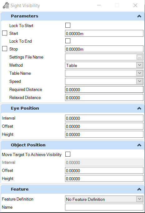
Sight Visibility
dialogue box
| Settings
|
Description
|
| Parameters
|
|
Lock to Start
|
|
Start
|
Specifies the start station for the first sight
line analysis.
Note: Set the
Stop Station to be less than the Start Station to analyze in the opposite
direction. When the Stop Station is less than the Start Station, the offsets
are relative to the direction of travel. Therefore, the sign of offsets
(negative or positive) do not need to be changed just because the direction of
travel changed.
|
|
Lock to End
|
|
Stop
|
Specifies the station for the last sight line
analysis.
Note: Set the
Stop Station to be less than the Start Station to analyze in the opposite
direction. When the Stop Station is less than the Start Station, the offsets
are relative to the direction of travel. Therefore, the sign of offsets
(negative or positive) do not need to be changed just because the direction of
travel changed.
|
|
Settings File Name
|
Specifies the file to be used that pre-populates
the settings on the dialog box. The actual settings on the dialog box are used
when the tool is executed. The settings file is only used as a quick way to
pre-populate the dialog box.
|
|
Visibility Type
|
Lists all the Speed Tables found in the Settings
File. Changing the Visibility Type changes the list of available Speed Table
Entries. Also, the Eye Position and Object Position settings for Move Target,
Interval, Offset and Height are changed when the Visibility Type are changed.
|
|
Speed
|
Lists all the Speed Table Entries found in the
Settings File that correspond to the selected Visibility Type. Changing the
speed changes Required Distance and Relaxed Distance based on the Visibility
Type and Speed selected.
|
|
Required Distance
|
Specifies the sight distance that must be
achieved.
|
| Settings
|
Description
|
|
Relaxed Distance
|
Specifies a sight distance that is considered a
relaxed distance if the achieved sight distance is greater than or equal to the
Relaxed Sight Distance and also less than required sight distance.
|
| Settings
|
Description
|
|
Eye Position
|
The Eye position's xy location is calculated by
projecting the station along the Control Reference to the Eye Reference
alignment and then applying the offset. The elevation used for the Eye Position
is determined by the elevation of the specified design surface at the Eye
Position's xy location.
|
|
Interval
|
Specifies the interval along Control Alignment at
which sight line calculations are made.
|
|
Offset
|
Specifies an offset from the Eye Reference
alignment. A negative offset is to the left of the Eye Reference alignment
relative to the direction of travel.
|
|
Height
|
Specifies the value by which the eye position
elevation is offset from the highest selected surface.
|
| Settings
|
Description
|
|
Object Position
|
|
Move Target to Achieve Visibility
|
The Object position's XY location is calculated
similar to the Eye Position. However, for object position, the location is down
range from the Eye Position along the Control Reference alignment a distance
equal to the Required Distance.
Note: When Move
Target is On a sight line for each Object Position Interval is analyzed until
the Required distance is either achieved for that Eye Position or an
intersection with a design or exiting terrain or mesh is found. In the case
where an intersection is found and the Required Sight Distance has not been
achieved, the analysis displays the last successful sight line for that eye
position.
|
|
Interval
|
Specifies the interval along Control Alignment
at which sight line calculations are made.
Note: Only used
when Move Target is Off.
|
|
Offset
|
Specifies an offset from the Object Reference
alignment. A negative offset is to the left of the Object Reference alignment
relative to the direction of travel.
|
|
Height
|
Specifies the value by which the object position
elevation is offset from the highest selected surface.
|
| Settings
|
Description
|
| Features
|
|
Feature Definition
|
Choose the feature definition that describes the
element being created.
Used as a basis for symbology of the created
element.
|
|
Name
|
Name of created element, default based on Feature
Definition settings. Override this with a new name if needed.
|
Sight Visibility Workflow
Step 1- Select Settings File (*.xml).
Step 2 - Select Method (workflow will change based
on the method selected, follow prompts).
Step 3- Enter Speed value.
Step 4- Specify Required Distance.
Step 5 - Specify Relaxed Distance.
Step 6- Locate a corridor or alignment.
Step 7- Locate Eye Control Alignment: Specify
centerline or another feature or Reset for Main Alignment.
Step 8- Locate Object Control Alignment: Specify
centerline or another feature or Reset for Main Alignment.
Step 9 - Specify Start Station (<Alt> Lock
to Start).
Step 10 - Specify End Station (<Alt> Lock to
End).
Step 11- Specify the eye position: interval,
heigh, offset from centerline.
Step 12 - Specify Object Position: Check on or off
"Move target to achieve Visibility", specify Offset and Height.
Step 13- Locate Existing Surface or Reset to Skip.
Step 14 - Sight Visibility Results displays.